The Signal Generators
The signal generator, or signal source, is the stimulus source that pairs with an acquisition instrument to create the two elements of a complete measurement solution. The two tools flank the input and output terminals of the device-under-test (DUT). In its various configurations, the signal generator can provide stimulus signals in the form of analog waveforms, digital data patterns, modulation, intentional distortion, noise, and more. To make effective design, characterization, or troubleshooting measurements, it is important to consider both elements of the solution.
This Application Note was written by Tektronix (Copyright). To read the full Application Note used this link (Tektronix web site):
http://www.physics.fsu.edu/users/Wahl/labmanuals/instruments/other/XYZofSignalSources.pdf
http://www.physics.fsu.edu/users/Wahl/labmanuals/instruments/other/XYZofSignalSources.pdf
The signal generator can provide “ideal” waveforms or it may add known, repeatable amounts and types of distortion (or errors) to the signal it delivers. This characteristic is one of the signal generator’s greatest virtues, since it is often impossible to create predictable distortion exactly when and where it’s needed using only the circuit itself. The response of the DUT in the presence of these distorted signals reveals its ability to handle stresses that fall outside the normal performance envelope.
Analog or Digital?
Most signal generators today are based on digital technology. Many can fulfill both analog and digital requirements, although the most efficient solution is usually a source whose features are optimized for the application at hand — either analog or digital. Arbitrary waveform generators (AWG) and function generators are aimed primarily at analog and mixed-signal applications. These instruments use sampling techniques to build and modify waveforms of almost any imaginable shape. Typically these generators have from 1 to 4 outputs. In some AWGs, these main sampled analog outputs are supplemented by separate marker outputs (to aid triggering of external instruments) and synchronous digital outputs that present sample-by-sample data in digital form. Digital waveform generators (logic sources) encompass two classes of instruments. Pulse generators drive a stream of square waves or pulses from a small number of outputs, usually at very high frequencies. These tools are most commonly used to exercise high-speed digital equipment. Pattern generators, also known as data generators or data timing generators, typically provide 8, 16, or even more synchronized digital pulse streams as a stimulus signal for computer buses, digital telecom elements, and more.
Basic Signal Generator Applications
Signal generators have hundreds of different applications but in the electronic measurement context they fall into three basic categories: verification, characterization, and stress/margin testing. Some representative applications include:
Verification – Testing Digital Modular Transmitters and Receivers
Wireless equipment designers developing new transmitter and receiver hardware must simulate baseband I&Q signals — with and without impairments — to verify conformance with emerging and proprietary wireless standards. Some high-performance arbitrary waveform generators can provide the needed lowdistortion, high-resolution signals at rates up to 1 gigabit per second (1 Gbps), with two independent channels, one for the “I” phase and one for the “Q” phase. Sometimes the actual RF signal is needed to test a receiver. In this case, arbitrary waveform generators with sample rates up to 200 S/s can be used to directly synthesize the RF signal.
Characterization – Testing D/A and A/D Converters
Newly-developed digital-to-analog converters (DAC) and analog to- digital converters (ADC) must be exhaustively tested to determine their limits of linearity, monotonicity, and distortion. A state-of-the-art AWG can generate simultaneous, in-phase analog and digital signals to drive such devices at speeds up to 1 Gbps.
Understanding Waveforms
Waveform Characteristics
The term “wave” can be defined as a pattern of varying quantitative values that repeats over some interval of time. Waves are common in nature: sound waves, brain waves, ocean waves, light waves, voltage waves, and many more. All are periodically repeating phenomena. Signal generators are usually concerned with producing electrical (typically voltage) waves that repeat in a controllable manner. Each full repetition of a wave is known as a “cycle.” A waveform is a graphic representation of the wave’s activity — its variation over time. A voltage waveform is a classic Cartesian graph with time on the horizontal axis and voltage on the vertical axis. Note that some instruments can capture or produce current waveforms, power waveforms, or other alternatives. In this document we will concentrate on the conventional voltage vs. time waveform.
Amplitude, Frequency and Phase
Waveforms have many characteristics but their key properties pertain to amplitude, frequency, and phase:
Amplitude: A measure of the voltage “strength” of the waveform. Amplitude is constantly changing in an AC signal. Signal generators allow you to set a voltage range, for example, -3 to +3 volts. This will produce a signal that fluctuates between the two voltage values, with the rate of change dependent upon both the wave shape and the frequency.
Frequency: The rate at which full waveform cycles occur. Frequency is measured in Hertz (Hz), formerly known as cycles per second. Frequency is inversely related to the period (or wavelength) of the waveform, which is a measure of the distance between two similar peaks on adjacent waves. Higher frequencies have shorter periods.
Phase: In theory, the placement of a waveform cycle relative to a 0 degree point. In practice, phase is the time placement of a cycle relative to a reference waveform or point in time.
Phase is best explained by looking at a sine wave. The voltage level of sine waves is mathematically related to circular motion. Like a full circle, one cycle of a sine wave travels through 360 degrees. The phase angle of a sine wave describes how much of its period has elapsed.
Two waveforms may have identical frequency and amplitude and still differ in phase. Phase shift, also known as delay, describes the difference in timing between two otherwise similar signals. Phase shifts are common in electronics. The amplitude, frequency, and phase characteristics of a waveform are the building blocks a signal generator uses to optimize waveforms for almost any application. In addition, there are other parameters that further define signals, and these too are implemented as controlled variables in many signal generators.
Rise and Fall Time
Edge transition times, also referred to as rise and fall times, are characteristics usually ascribed to pulses and square waves. They are measures of the time it takes the signal edge to make a transition from one state to another. In modern digital circuitry, these values are usually in the low nanosecond range or less.
Both rise and fall times are measured between the 10% and 90% points of the static voltage levels before and after the transition (20% and 80% points are sometimes used as alternatives). This is an image of the type you would see on an oscilloscope set at a high sample rate relative to the frequency of the incoming signal. At a lower sample rate, this same waveform would look much more “square.” In some cases, rise and fall times of generated pulses need to be varied independently, for example when using generated pulses to measure an amplifier with unsymmetrical slew rates, or controlling the cool down time of a laser spot welding gun.
Pulse Width
Pulse width is the time that elapses between the leading and trailing edges of a pulse. Note that the term “leading” applies to either positive-going or negative-going edges as does the term “trailing.” In other words, these terms denote the order in which the events occur during a given cycle; a pulse’s polarity does not affect its status as the leading or trailing edge. The pulse width measurement expressed the time between the 50% amplitude points of the respective edges.
Another term, “duty cycle,” is used to describe a pulse’s high and low (on/off) time intervals. In contrast, a cycle with a period of 100 ns whose active high (on) level lasts 60 ns is said to have a 60% duty cycle. To cite a tangible example of a duty cycle, imagine an actuator that must rest for three seconds after each one-second burst of activity, in order to prevent the motor from overheating. The actuator rests for three seconds out of every four — a 25% duty cycle.
Offset
Not all signals have their amplitude variations centered on
a ground (0 V) reference. The “offset” voltage is the voltage between circuit ground and the center of the signal’s amplitude. In effect, the offset voltage expresses the DC component of a signal containing both AC and DC values.
Differential vs. Single-ended Signals
Differential signals are those that use two complementary paths carrying copies of the same signal in equal and opposite polarity (relative to ground). As the signal’s cycle proceeds and the one path becomes more positive, the other becomes more negative to the same degree. For example, if the signal’s value at some instant in time was +1.5 volts on one of the paths, then the value on the other path would be exactly -1.5 volts (assuming the two signals were perfectly in phase). The differential architecture is good at rejecting crosstalk and noise and passing only the valid signal. Single-ended operation is a more common architecture, in which there is only one path plus ground.
Basic Waves
Waveforms come in many shapes and forms. Most electronic measurements use one or more of the following wave shapes, often with noise or distortion added:
Sine Waves
Sine waves are perhaps the most recognizable wave shape. Most AC power sources produce sine waves. Household wall outlets deliver power in the form of sine waves. And the sine wave is almost always used in elementary classroom demonstrations of electrical and electronic principles. The sine wave is the result of a basic mathematical function — graphing a sine curve through 360 degrees will produce a definitive sine wave image.
The damped sine wave is a special case in which a circuit oscillates from an impulse, and then winds down over time.
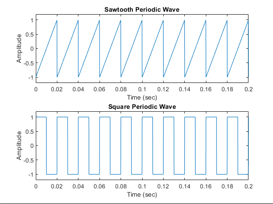
Square And Rectangular Waves
Square and rectangular waves are basic forms that are at the heart of all digital electronics, and they have other uses as well. A square wave is a voltage that switches between two fixed voltage levels at equal intervals. It is routinely used to test amplifiers, which should be able to reproduce the fast transitions between the two voltage levels (these are the rise and fall times explained earlier). The square wave makes an ideal timekeeping clock for digital systems — computers, wireless telecom equipment, HDTV systems, and more. A rectangular wave has switching characteristics similar to those of a square wave, except that its high and low time intervals are not of equal length, as described in the earlier “duty cycle” explanation.
Sawtooth and Triangle Waves
Sawtooth and triangle waves look very much like the geometric shapes they are named for. The sawtooth ramps up slowly and evenly to a peak in each cycle, then falls off quickly. The triangle has more symmetrical rise and fall times. These waveforms are often used to control other voltages in systems such as analog oscilloscopes and televisions.
Step and Pulse Shapes
A “step” is simply a waveform that shows a sudden change in voltage, as though a power switch had been turned on. The “pulse” is related to the rectangular wave. Like the rectangle, it is produced by switching up and then down, or down and then up, between two fixed voltage levels. Pulses are inherently binary and therefore are the basic tool for carrying information (data) in digital systems. A pulse might represent one bit of information traveling through a computer. A collection of pulses traveling together creates a pulse train. A synchronized group of pulse trains (which may be transmitted in parallel or serial fashion) makes up a digital pattern.
Note that, while digital data is nominally made up of pulses, rectangles, and square waves, real-world digital waveforms exhibit more rounded corners and slanted edges. Sometimes, circuit anomalies produce pulses spontaneously. Usually these transient signals occur non-periodically, and have come to be described with the term “glitch.” One of the challenges of digital troubleshooting is distinguishing glitch pulses from valid but narrow data pulses. And one of the strengths of certain types of signal generators is their ability to add glitches anywhere in a pulse train.
Complex Waves
In operational electronic systems, waveforms rarely look like the textbook examples explained above. Certain clock and carrier signals are pure, but most other waveforms will exhibit some unintended distortion (a by-product of circuit realities like distributed capacitance, crosstalk, and more) or deliberate modulation. Some waveforms may even include elements of sines, squares, steps, and pulses.
Complex waves include:
Analog modulated, digitally modulated, pulse-width modulated, and quadrature modulated signals
Digital patterns and formats
Pseudo-random bit and word streams
Signal Modulation
In modulated signals, amplitude, phase and/or frequency variations embed lower-frequency information into a carrier signal of higher frequency. The resulting signals may convey anything from speech to data to video. The waveforms can be a challenge to reproduce unless the signal generator is specifically equipped to do so.
Analog Modulation.
Amplitude modulation (AM) and frequency modulation (FM) are most commonly used in broadcast communications. The modulating signal varies the carrier’s amplitude and/or frequency. At the receiving end, demodulating circuits interpret the amplitude and/or frequency variations, and extract the content from the carrier. Phase modulation (PM) modulates the phase rather than the frequency of the carrier waveform to embed the content.
Digital Modulation.
Digital modulation, like other digital technologies, is based on two states which allow the signal to express binary data. In amplitude-shift keying (ASK), the digital modulating signal causes the output frequency to switch between two amplitudes; in frequency-shift keying (FSK), the carrier switches between two frequencies (its center frequency and an offset frequency); and in phase-shift keying (PSK), the carrier switches between two phase settings. In PSK, a “0” is imparted by sending a signal of the same phase as the previous signal, while a “1” bit is represented by sending a signal of the opposite phase. Pulse-width modulation (PWM) is yet another common digital format; it is often used in digital audio systems. As its name implies, it is applicable to pulse waveforms only. With PWM, the modulating signal causes the active pulse width (duty cycle, explained earlier) of the pulse to vary.
Frequency Sweep
Measuring the frequency characteristics of an electronic device calls for a “swept” sine wave — one that changes in frequency over a period of time. The frequency change occurs linearly in “Hz per seconds” or logarithmically in “Octaves per second.” Advanced sweep generators support sweep sequences with selectable start frequency, hold frequency, stop frequency and associated times. The signal generator also provides a trigger signal synchronously to the sweep to control an oscilloscope that measures the output response of the device.
Quadrature Modulation.
Today’s digital wireless communications networks are built on a foundation of quadrature (IQ) modulation technology. Two carriers — an in-phase (I) waveform and a quadrature-phase (Q) waveform that is delayed by exactly 90 degrees relative to the “I” waveform — are modulated to produce four states of information. The two carriers are combined and transmitted over one channel, then separated and demodulated at the receiving end. The IQ format delivers far more information than other forms of analog and digital modulation: it increases the effective bandwidth of the system.
Digital Patterns and Formats
A digital pattern consists of multiple synchronized pulse streams that make up “words” of data that may be 8, 12, 16, or more bits wide. One class of signal generator, the digital pattern generator, specializes in delivering words of data to digital buses and processors via parallel outputs. The words in these patterns are transmitted in a steady march of cycles, with the activity for each bit in each cycle determined by the chosen signal format. The formats affect the width of the pulses within the cycles that compose the data streams.
© Copyright © 2003, Tektronix, Inc. All rights reserved.

Mr WordPress
18 Jun 2010Hi, this is a comment.
To delete a comment, just log in and view the post's comments. There you will have the option to edit or delete them.