General Connector Information
Many coaxial connector types are available in the RF and microwave industry, each designed for a specific purpose and application. For measurement applications, it is important to consider the number of connects/disconnects, which impact the connector’s useful life. The frequency range of any connector is limited by the excitation of the first circular waveguide propagation mode in the coaxial structure. Decreasing the diameter of the outer conductor increases the highest usable frequency; filling the air space with dielectric lowers the highest usable frequency and increases system loss.
Performance of all connectors is affected by the quality of the interface for the mated pair. If the diameters of the inner and outer conductors vary from the nominal design, if plating quality is poor, or if contact separation at the junction is excessive, then the reflection coefficient and resistive loss at the interface will be degraded.
A few connectors, such as the APC-7, are designed to be sexless. Most are female connectors that have slotted fingers, which introduce a small inductance at the interface. The fingers accommodate tolerance variations but reduce repeatability and may ultimately break after 1000 connections.
The following is a brief review of common connectors used in test and measurement applications
This Application Note was written by Agilent (Copyright). To read the full Application Note used this link (agilent web site):
Coaxial Connector Overview.pdf
APC-7 (7 mm) connector
The APC-7 (Amphenol Precision Connector-7 mm) offers the lowest reflection coefficient and most repeatable measurement of all 18 GHz connectors. Development of the connector was a joint effort between HP and Amphenol, which began in the 1960s. This is a sexless design and is the preferred connector for the most demanding applications, notably metrology and calibration.
Type-N connector
The type-N (Navy) 50-ohm connector was designed in the 1940s for military systems operating below 4 GHz. In the 1960s, improvements pushed performance to 12 GHz and later, mode-free, to 18 GHz. Agilent offers some products with slotless type-N center conductors for improved performance to 18 GHz. Agilent type-N connectors are completely compatible with MIL-C-39012. Certain 75-ohm products use a type-N design with smaller center conductor diameters, and thus are not compatible with 50-ohm connectors.
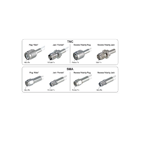
SMA connector
The SMA (Subminiature A) connector was designed by Bendix Scintilla Corporation and is one of the most commonly used RF/microwave connectors. It is intended for use on semirigid cables and in components that are connected infrequently. Most SMA connectors have higher reflection coefficients than other connectors available for use to 24 GHz because of the difficulty to anchor the dielectric support.
3.5-mm connector
The 3.5-mm connector was primarily developed at Hewlett Packard—now Agilent Technologies, with early manufacturing at Amphenol. Its design strategy focused on highly-rugged physical interfaces that would mate with popular SMA dimensions, allowing thousands of repeatable connections. It is mode-free to 34 GHz.
1.0-mm launch
The launch adapter has a 1.0-mm female connector on one end and a glass to metal seal interface on the other end. This is for transition of ultra-high frequency (up to 110 GHz) signals from coax into a microstrip package or onto a circuit board.
2.92-mm connector
The 2.92-mm connector mates with SMA and 3.5-mm connectors and offers mode-free performance to 40 GHz.
2.4-mm connector
The 2.4-mm connector was developed by HP, Amphenol, and M/A-COM for use to 50 GHz. This design eliminates the fragility of the SMA and 2.92-mm connectors by increasing the outer wall thickness and strengthening the female fingers. It can mate with SMA, 3.5-mm and 2.92-mm with the use of precision adapters. The 2.4-mm product is offered in three quality grades; general purpose, instrument, and metrology. General purpose grade is intended for economy use on components, cables, and microstrip, where limited connections and low repeatability is acceptable. Instrument grade is best suited for measurement applications where repeatability and long life are primary considerations. Metrology grade is best suited for calibration applications where the highest performance and repeatability are required.
1.85-mm Connector
The 1.85-mm connector was developed in the mid-1980s by Hewlett Packard— now Agilent Technologies—for mode-free performance to 65 GHz. HP offered their design as public domain in 1988 to encourage standardization of connector types; a few devices are available from various manufacturers for research work. The 1.85-mm connector mates with the 2.4-mm connector and has the same ruggedness. Many experts have considered this connector to be the smallest possible coaxial connector for common usage up to 65 GHz.
1.0-mm connector
Designed to support transmission all the way to 110 GHz, this 1.0-mm connector is a significant achievement in precision manufacturing resulting in a reliable and flexible interconnect.
BNC connector
The BNC (Bayonet Navy Connector) was designed for military use and has gained wide acceptance in video and RF applications to 2 GHz. Above 4 GHz, the slots may radiate signals. Both 50-ohm and 75-ohm versions are available. A threaded version (TNC) helps resolve leakage for common applications up to 12 GHz.
SMC connector
The SMC (Subminiature C) is much smaller than an SMA connector, making it suitable for some applications with size constraints. It is often used up to 7 GHz where low leakage and few connections are required.
Recommended torque values for connectors
Precision 7 mm = 136 (N-cm)
Precision 3.5 mm = 90 (N-cm)
SMA = 56 (N-cm)
Precision 2.4 mm = 90 (N-cm)
Precision 2.4 mm = 90 (N-cm)
Type-N = 136 (N-cm)
© Agilent Technologies, Inc.
Some material in this appendix is reproduced with permission from Agilent technologies