At first glance, an electronic counter seems like a fairly simple instrument. You connect a signal to the input, and a digital readout tells you the frequency or some other parameter.
While we’d like to say that counters are a plug-in-and-go sort of instrument, the technical realities of quartz-crystal timebases demand some care and attention on your part.
The counter, its timebase options, your signal, and the way you set up the measurement all affect the quality of the results. In fact, so many factors play into the equation that the accuracy specification for a good counter is literally that—an equation. The good news is that a little attention goes a long way toward better measurements, and these eight hints are a great place to start.
Hint 1: Understand the effects of counter architecture
RF counters fall into two basic categories: direct counting and reciprocal counting. Understanding the effects of the two difference approaches will help you choose the correct counter and use it correctly.
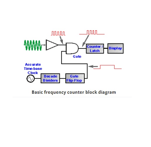
Direct counters simply count the number of times the input signal crosses zero during a specific gate time. The resulting count is sent directly to the counter’s readout for display. This method is simple and inexpensive, but it means that the direct counter’s resolution is fixed in Hertz.
Reciprocal counters, in contrast, measure the input signal’s period, then reciprocate it to get frequency. Thanks to the measurement architecture involved, the resulting resolution is fixed in the number of digits displayed (not Hertz) for a given gate time. In other words, a reciprocal counter will always display the same number of digits of resolution regardless of the input frequency. You’ll see the resolution of a reciprocal counter specified in terms of the number of digits for a particular gate time, such as “10 digits per second.”
Hint 2: Recognize the difference between resolution and accuracy
Equating resolution with accuracy is a common mistake, they are related, but they are distinctly different concepts. Resolution can be defined as the counter’s ability to distinguish closely spaced frequencies. All other things being equal (such as measurement time and product cost), more digits are better—but the digits you see on the display need to be supported by accuracy. Digits can be deceptive when other errors push the counter’s resolving ability away from the actual frequency. In other words, it’s possible for a counter to give you a very precise reading of an incorrect frequency. True measurement accuracy is a function of both random and systematic errors.
Hint 3: Choose the most appropriate timebase
Measurement accuracy in frequency counters begins with the timebase because it establishes the reference against which your input signal is measured. The better the timebase, the better your measurements can be.
Hint 4: Adjust sensitivity to avoid noise triggering
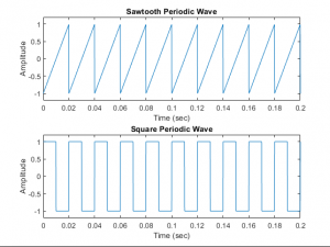
The good news is that high quality counters are broadband instruments with sensitive input circuits. That’s also the bad news. To a counter, all signals basically look the same. Sine waves, square waves, harmonics, random noise – they all just look like a series of zero crossings as far as the counter is concerned. A counter figures out the signal’s frequency by triggering on these zero crossings to measure frequency. If your signal is clean and uncluttered, the process works quite well. Noisy signals, however, can trick the counter into triggering on spurious zero crossings. When this happens, the counter doesn’t count what you think it’s counting.
Hint 5: Configure your counter for low-frequency measurements
Problem of triggering on unwanted components in your signal. This problem can be even more acute with low frequency signals (roughly 100 Hz and below), since the chance of spurious triggering on irrelevant high-frequency components is that much greater. In addition, the signal’s slew rate affects trigger accuracy; the lower the slew rate, the more chance there is for error
Here are three quick steps you can take to help improve the quality of counter measurements on low-frequency signals.
A) Use the low-pass filter. B)Use manual triggering. C) Use dc coupling
Hint 6: Use statistics to characterize signals
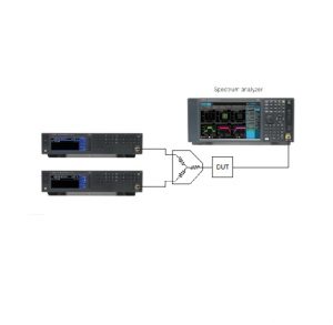
A good counter can do more for you than simply count. Built-in statistical functions help characterize signals and identify trends, two tasks you’d have to perform on a PC otherwise. A basic set of statistical functions includes arithmetic mean, minimum, maximum, and standard deviation. For example, a wandering carrier signal is a great application for counter statistics. Min, max, mean and standard deviation can give you a clear picture of the carrier’s behavior, without resorting to a spectrum analyzer. Moreover, the counter will give you better frequency resolution than you could get with a spectrum analyzer.
Hint 7: Schedule calibration
Hint 8: Smooth out jumper display
© Agilent Technologies, Inc. 2012, Published in USA, April 10, 2001, 5967-6038E
Some material in this appendix is reproduced with permission from Agilent technologies
Reproduced with Permission, Courtesy of Keysight technologies, Inc